

So I had asked for a DIY a bit ago for installing glowshift gauges and piller pod and wiring. Well I received some help, but I figured a DIY would be the best way to go for others interested in putting together these gauges and such.
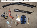
First off, the gauges I chose: I went with Glowshift Black 7's. I chose the A/F, Vaccum, and Volt gauges.
Needed for install:
Phillips and Flat head screwdrivers
Dremel or hand saw or drill (I found it easiest to use my dremel.)
Electrical wire (to extend the wires for all gauges)
Soldering gun (best to make sure the connections stay together)
Needle nose pliers
Patience!
Steps:
1. Choose which gauges you will use, and chose whether you want to do the tripple gauge piller or the double or the single. the install will be the same for all three, just depends on your number of gauges. (my choices listed above)
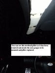
2. Next remove the driver's side piller. (it is held in with pop in clips) Just start at the top where the crease is and pull carefully until it all pop's free. You will need to do this in order to drill a hole to run the wiring and then run the wires behind the piller to hide them from sight.
3. Once you have decided on a mounting location, decide which gauges you would like where in the piller. Make sure you realize that different gauges are different lengths, so the piller will have to be trimmed to allow the backside of the gauge to slide through, otherwise it will not fit flush and will stick out and look like crap. Also at this time it is a good idea to tighten down your gauges as you will not need to have them off again.
4. Mark off the locations on the factory piller and carefully cut out the needed sections to fit the gauges properly. once you can fit the gauges properly it is time to begin the wiring and hoses (only with the vaccum or boost gauges).
5. As you can see in my pictures I did not want my vaccum hose line to be crimped once I put the piller back in place, so I decided to cut out a line of holes through the plastic on the backside of the piller and use it as a guide to run the hose through. (see pic below)
6. Once all of your lines are ran it is time to begin to connect and finalize your wiring for the piller. Take all of the same colored wires from each gauge (aka, yellow is to the 12v allways on source) and solder them all together. Then connect your extra wire to extend the wiring past the end of the piller. (so you can install the piller and get the wire later to hook up behind the dash.)
7. Once all wires have been extended, and any hoses ran it is time to tuck them behind the dash. You'll notice now with the piller still off that there is a section that you can push all the wiring and hoses through right where the dash meets the piller. Once this is done you can mount your Piller back onto your frame. (admire your work as you are now half done)
8.....(PAUSED FOR NOW) I stopped for today to watch the Superbowl..... I'll finish it all up next Saturday when I get home from my business trip and update accordingly on how to finish this DIY.
First off, the gauges I chose: I went with Glowshift Black 7's. I chose the A/F, Vaccum, and Volt gauges.
Needed for install:
Phillips and Flat head screwdrivers
Dremel or hand saw or drill (I found it easiest to use my dremel.)
Electrical wire (to extend the wires for all gauges)
Soldering gun (best to make sure the connections stay together)
Needle nose pliers
Patience!
Steps:
1. Choose which gauges you will use, and chose whether you want to do the tripple gauge piller or the double or the single. the install will be the same for all three, just depends on your number of gauges. (my choices listed above)
2. Next remove the driver's side piller. (it is held in with pop in clips) Just start at the top where the crease is and pull carefully until it all pop's free. You will need to do this in order to drill a hole to run the wiring and then run the wires behind the piller to hide them from sight.
3. Once you have decided on a mounting location, decide which gauges you would like where in the piller. Make sure you realize that different gauges are different lengths, so the piller will have to be trimmed to allow the backside of the gauge to slide through, otherwise it will not fit flush and will stick out and look like crap. Also at this time it is a good idea to tighten down your gauges as you will not need to have them off again.
4. Mark off the locations on the factory piller and carefully cut out the needed sections to fit the gauges properly. once you can fit the gauges properly it is time to begin the wiring and hoses (only with the vaccum or boost gauges).
5. As you can see in my pictures I did not want my vaccum hose line to be crimped once I put the piller back in place, so I decided to cut out a line of holes through the plastic on the backside of the piller and use it as a guide to run the hose through. (see pic below)
6. Once all of your lines are ran it is time to begin to connect and finalize your wiring for the piller. Take all of the same colored wires from each gauge (aka, yellow is to the 12v allways on source) and solder them all together. Then connect your extra wire to extend the wiring past the end of the piller. (so you can install the piller and get the wire later to hook up behind the dash.)
7. Once all wires have been extended, and any hoses ran it is time to tuck them behind the dash. You'll notice now with the piller still off that there is a section that you can push all the wiring and hoses through right where the dash meets the piller. Once this is done you can mount your Piller back onto your frame. (admire your work as you are now half done)
8.....(PAUSED FOR NOW) I stopped for today to watch the Superbowl..... I'll finish it all up next Saturday when I get home from my business trip and update accordingly on how to finish this DIY.


")