
MULTI GAUGE UNIT WIRING FOR 2003 TIBURON
![Image]()
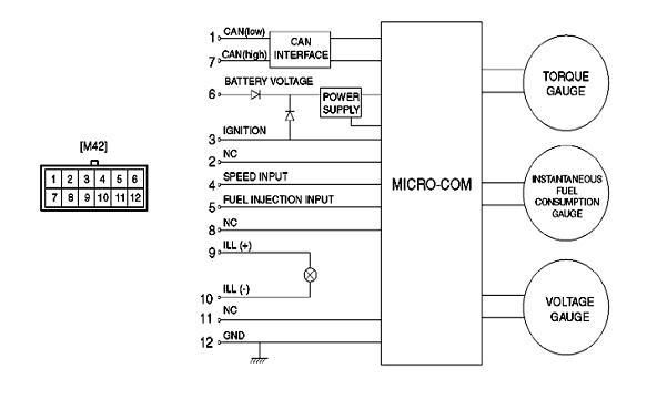
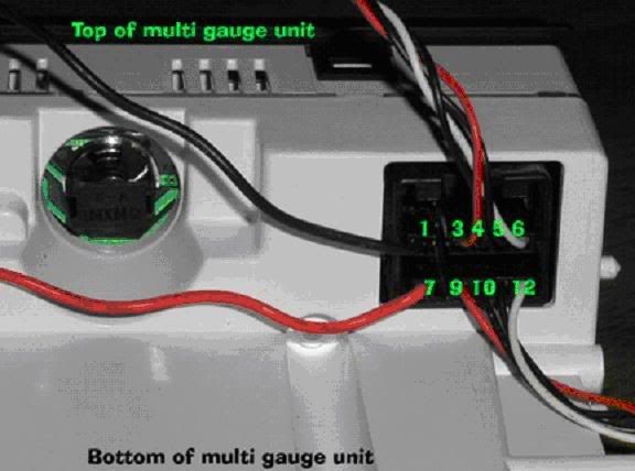
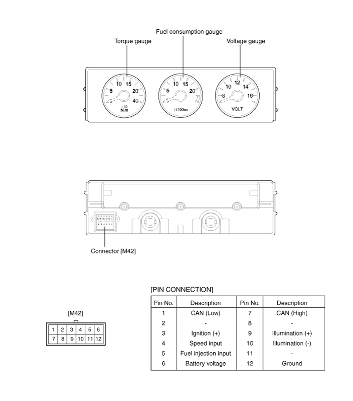
Pin 1 – Green wire at MC103 (Pin 3)
Pin 2 – Not Used
Pin 3 - Yellow wire at OEM radio harness
Pin 4 – Brown wire at MC101 (Pin 3) or Brown wire at M10-1 (Pin 17)
Pin 5 - Blue wire at MC101 (Pin 11) or Blue wire at M10-1 (Pin 2)
Pin 6 - Red wire at OEM radio harness
Pin 7 - Orange wire at MC103 (Pin 2)
Pin 8 – Not Used
Pin 9 - Pink/Black at OEM radio harness
Pin 10 - Grey wire at OEM radio harness
Pin 11 - Not Used
Pin 12 - Black wire at OEM radio harness or ANY GOOD GROUND
----------------------------------------------------------------------------------------------------------------------
![Image]()
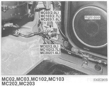
SPEED INPUT (pins 4 & 5 from multi gauges)
The Blue wire (goes to pin 5 on the gauges) is in the LOWER RIGHT hand corner of the connector MC101. If you are sitting in the driver’s seat and looking at the connector, it is the wire all the way to the right (passenger side) and on the bottom. It will be a Blue wire. A Red/Black wire will be to its left and a Brown wire will be right above it. Once you find this wire you can also look for the Brown wire (goes to pin 4 on the gauges). It is at Pin 3. Go up ONE wire and over TWO to the LEFT. You will see the Brown wire. It is the THIRD one in.
----------------------------------------------------------------------------------------------------------------------
![Image]()
These two wires can also be found in the gauge cluster as well in Connector M10-1. I pointed these locations out because it is rather difficult to work with the connector under the center console. I’ll leave the choice up to you which wires you use.
----------------------------------------------------------------------------------------------------------------------
![Image]()
CAN INTERFACE (pins 1 & 7 from the multi gauges)
The Green (goes to pin 1 on gauges) and Orange (goes to pin 7 on gauges) wires are in the UPPER RIGHT corner of the connector MC103. The connector is an 8 pin connector. They are right next to each other on the RIGHT side of the connector release tab. There are NO wires to the immediate LEFT or RIGHT of these wires. See for yourself.
----------------------------------------------------------------------------------------------------------------------
![Image]()
Pin 1 – Green wire at MC103 (Pin 3)
Pin 2 – Not Used
Pin 3 - Yellow wire at OEM radio harness
Pin 4 – Brown wire at MC101 (Pin 3) or Brown wire at M10-1 (Pin 17)
Pin 5 - Blue wire at MC101 (Pin 11) or Blue wire at M10-1 (Pin 2)
Pin 6 - Red wire at OEM radio harness
Pin 7 - Orange wire at MC103 (Pin 2)
Pin 8 – Not Used
Pin 9 - Pink/Black at OEM radio harness
Pin 10 - Grey wire at OEM radio harness
Pin 11 - Not Used
Pin 12 - Black wire at OEM radio harness or ANY GOOD GROUND
----------------------------------------------------------------------------------------------------------------------

SPEED INPUT (pins 4 & 5 from multi gauges)
The Blue wire (goes to pin 5 on the gauges) is in the LOWER RIGHT hand corner of the connector MC101. If you are sitting in the driver’s seat and looking at the connector, it is the wire all the way to the right (passenger side) and on the bottom. It will be a Blue wire. A Red/Black wire will be to its left and a Brown wire will be right above it. Once you find this wire you can also look for the Brown wire (goes to pin 4 on the gauges). It is at Pin 3. Go up ONE wire and over TWO to the LEFT. You will see the Brown wire. It is the THIRD one in.
----------------------------------------------------------------------------------------------------------------------

These two wires can also be found in the gauge cluster as well in Connector M10-1. I pointed these locations out because it is rather difficult to work with the connector under the center console. I’ll leave the choice up to you which wires you use.
----------------------------------------------------------------------------------------------------------------------
CAN INTERFACE (pins 1 & 7 from the multi gauges)
The Green (goes to pin 1 on gauges) and Orange (goes to pin 7 on gauges) wires are in the UPPER RIGHT corner of the connector MC103. The connector is an 8 pin connector. They are right next to each other on the RIGHT side of the connector release tab. There are NO wires to the immediate LEFT or RIGHT of these wires. See for yourself.
----------------------------------------------------------------------------------------------------------------------
Pin 1 – Green wire at MC103 (Pin 3)
Pin 2 – Not Used
Pin 3 - Yellow wire at OEM radio harness
Pin 4 – Brown wire at MC101 (Pin 3) or Brown wire at M10-1 (Pin 17)
Pin 5 - Blue wire at MC101 (Pin 11) or Blue wire at M10-1 (Pin 2)
Pin 6 - Red wire at OEM radio harness
Pin 7 - Orange wire at MC103 (Pin 2)
Pin 8 – Not Used
Pin 9 - Pink/Black at OEM radio harness
Pin 10 - Grey wire at OEM radio harness
Pin 11 - Not Used
Pin 12 - Black wire at OEM radio harness or ANY GOOD GROUND
 , nah i would just triple check all the connections, prolly just missing one somewhere.