
Ok, here it is, my first DIY on this forum, so bear with me. I don't seem to be able to post in the DIY section myself so maybe a moderator will be so kind as to relocate this thread. Thanks.
First off, please read the entire post before starting to pull plugs and cut wires. I don't want you to find out halfway through the process there is something missing and have you end up with a non-working HVAC until new parts arrive.
This is a DIY for converting your 2003 model automatic climate control unit into the F/L2 unit. It should also work for the 04, 05 and 06 cars, they are all wired exactly the same way.
What do you need to perform this conversion:
- Obviously you'll need a F/L2 center facia with the auto climate control unit and the clock & switch module. I bought mine used off eBay.
- You'll also need the plugs that go with the new unit. There are two plugs (called MI19-1 and MI19-2) for the HVAC and one (M22) for the clock & switch module. The MI19-1 fits the new unit, the MI19-2 doesn't.
- Field Effect Transistor for operating the blower motor. The part number for this FET is 97235-1E000.
- Soldering iron.
- Wire cutter.
- Small tool to release the little pins from the Molex plugs. I used a very small hex-tool for the larger pins and a thin nail for the smaller ones.
- Philips screwdriver.
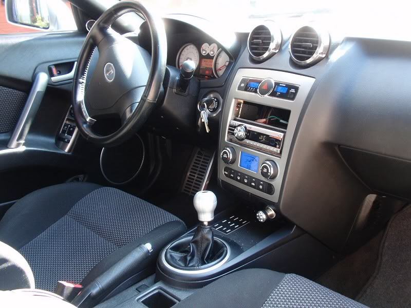
![Image]()
Before you start I recommend disconnecting the negative battery connector to avoid short circuiting. You will need the so called "hot at all times" wires and you don't want to blow any fuses.
Let's take a look at the schematics before we begin. It helps when you understand what you are doing")
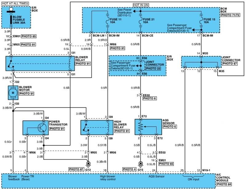
This is the situation for the 2003 climate control. Notice how the blower motor is controlled by a power transistor and a high blower relay.
![Image]()
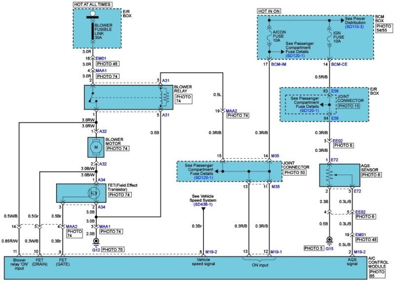
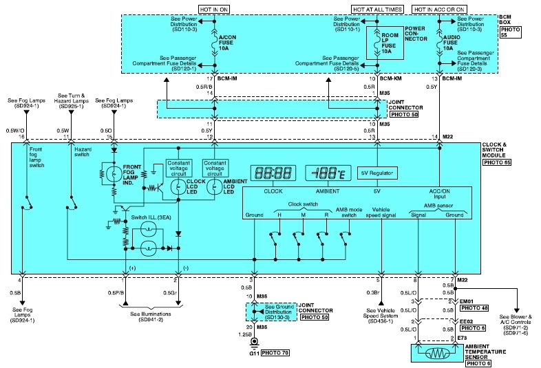
Here's we have the picture for the 2007 climate control. Here a Field Effect Transistor controls the blower instead.
![Image]()
The changes we are going to make are shown in this picture. When we replace the transistor with the FET and delete the high blower relay, all that is left is to short the wires operated the relay. There will be an extra 10A fuse in the "blower relay input" line compared to the normal 2007 schematic, but that never hurts.
![Image]()
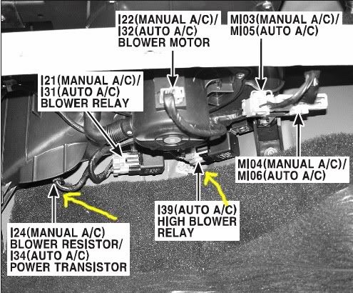
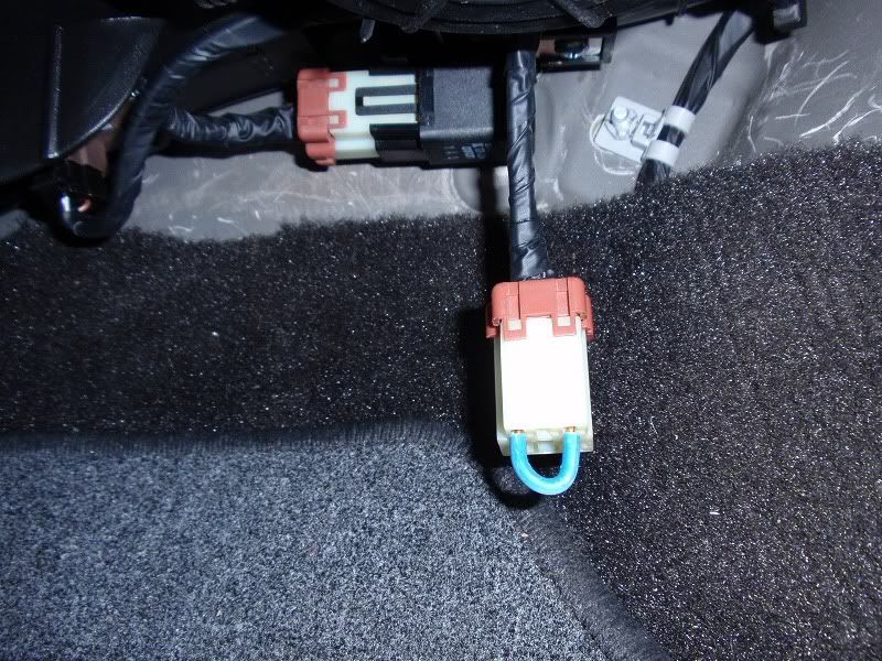
So, use this picture to locate the transistor and the high blower relay. Replace the transistor with your FET and remove the relay. Now short the two pin of the relay connector that are closest to each other. You can also look at the wires at the back to find out which. There are noticable thinner, colors should be Red and Yellow/Black. I just stuck a thick piece of wire in them.
![Image]()
![Image]()
Now take out the center facia from your car. Open up the ashtray to get your fingers behind the bottom left corner and start pulling. There are 6 clips holding it in place. Work your way up pulling all of the clips out. Disconnect the plugs from the rear. At the top there are the foglight, hazard and clock plugs, at the bottom there are the two MI19 plugs.
You don't really need to remove the multi-gauge unit and audio at this point but if you want some more space to work with and you don't mind disconnecting them, go ahead.
The next part is a little time consuming but not difficult. Just keep focussed on what you are doing. When you look at the back of the bigger MI19-1 plug you'll notice there are some larger pins on the sides (1,2,3,12,13,14,15,16,25 & 26) and smaller ones in the middle. The MI19-2 has all small pins.
![Image]()
The new MI19-2 plug does have the larger pins as well (1,10,11,12,21 & 22).
![Image]()
Please note that all plugs are displayed here looking at the front-side. You'll be mostly looking at the back of these plugs so numbering then starts at the top left.
All of the wires of the old MI19-1 and MI19-2 plugs need to be transferred to different locations on the new plugs. Some of them can be transplanted just like that, others need to have another pin (larger or smaller) attached. If that's the case you'll need to cut the wire and solder another pin back on. I recommend starting with the pins that can be relocated as-is before doing the cutting and soldering.
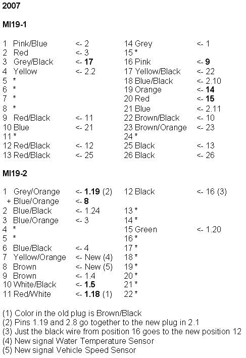
Here's the instructions for the rewiring. The numbers in bold require soldering different pins on. You'll see some wires go from plug MI19-1 to MI19-2 and vice versa, they are indicated as 1.4 for pin 4 on plug 1 or 2.11 for pin 11 on plug 2. I hope this makes sense and these instructions are understandable this way.
![Image]()
You'll notice there are a few wires that are no longer needed for the F/L2 climate control. Appearantly the new one doesn't use the humidity sensor anymore.
Also look at the layout for the new situation:
![Image]()
There are two signals that the new climate control uses and the old one doesn't. I didn't connect the Water Temperature Sensor wire. It doesn't seem to affect the HVAC operation. If some serious problem arises because of the lack of this signal I'll have to look into retrieving the information from the coolant temperature sensor. I did however connect the Vehicle Speed Sensor wire. This can easily be retrieved from the multi gauge unit.
Multi Gauge Unit plug. Again this is the frontside.
![Image]()
The brown wire (pin 4) is the one you need for the Vehicle Speed Sensor. Use a piece of (preferably brown) wire to attach to this one and solder a small pin at the other end. This goes into pin 8 of the MI19-2 plug. However, the clock & switch module for some reason uses the speed sensor as well so when you do this you should also connect a wire to the clock & switch module plug, which I will now describe in more detail.
![Image]()
The old center facia has all the buttons and clock as separate items sticking in it. The new one has just one clock and switch module which contains the foglight switch, hazard switch, clock and outside temperature display. There is also just one 16-pin plug for it.
Clock & Switch Module plug (frontside)
![Image]()
I was unable to release the small pins in this plug. All I had was a plug with pieces of wires sticking out of it so I just went ahead and soldered all of those wires. You will need the wires from these existing plugs:
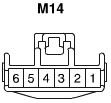
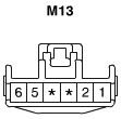
Clock plug.
![Image]()
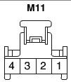
Front Foglight switch plug.
![Image]()
Hazard switch plug.
![Image]()
Here's how to wire them:
M22
1 Pink/Black <- Illumination <- Foglight pin 2
2 Grey <- Illumination <- Foglight pin 1
3 Black <- Ground <- Foglight pin 3
4 Black <- Foglight switch <- Foglight pin 6
5 Brown <- Vehicle Speed Sensor <- Multigauge pin 4
6 *
7 Black <- Ambient Temperature Sensor <- See below !
8 Blue/Orange <- Ambient Temperature Sensor <- See below !
9 *
10 *
11 White <- Hazard switch <- Hazard pin 6
12 Yellow <- Hot In On <- Clock pin 4
13 Red <- Hot At All Times <- Clock pin 2
14 Yellow <- Hot In Acc Or On <- Clock pin 4
15 Orange <- Foglight Indicator <- Foglight pin 4
16 White/Orange <- Foglight switch <- Foglight pin 5
Since the Clock & Switch module displays the ambient temperature it needs this input. Simply take the signal from the climate control. Attach some wire (preferably one black and one blue) to those at the MI19-2 plug pins 3 (blue) and 12 (black). Pin 3 contains the actual signal and 12 is ground to all sensors. Connect the blue wire to the Clock & Switch plug pin 8 and the black wire to pin 7.
![Image]()
That's it! Now just plug everything in again and reinstall the center facia. Don't forget to reconnect the battery
Hopefully this DIY contains enough detail for anyone to work with. If you have questions for me I'd be more than happy to answer to the best of my ability.
One more picture of the final result:
![Image]()
First off, please read the entire post before starting to pull plugs and cut wires. I don't want you to find out halfway through the process there is something missing and have you end up with a non-working HVAC until new parts arrive.
This is a DIY for converting your 2003 model automatic climate control unit into the F/L2 unit. It should also work for the 04, 05 and 06 cars, they are all wired exactly the same way.
What do you need to perform this conversion:
- Obviously you'll need a F/L2 center facia with the auto climate control unit and the clock & switch module. I bought mine used off eBay.
- You'll also need the plugs that go with the new unit. There are two plugs (called MI19-1 and MI19-2) for the HVAC and one (M22) for the clock & switch module. The MI19-1 fits the new unit, the MI19-2 doesn't.
- Field Effect Transistor for operating the blower motor. The part number for this FET is 97235-1E000.
- Soldering iron.
- Wire cutter.
- Small tool to release the little pins from the Molex plugs. I used a very small hex-tool for the larger pins and a thin nail for the smaller ones.
- Philips screwdriver.

Before you start I recommend disconnecting the negative battery connector to avoid short circuiting. You will need the so called "hot at all times" wires and you don't want to blow any fuses.
Let's take a look at the schematics before we begin. It helps when you understand what you are doing
This is the situation for the 2003 climate control. Notice how the blower motor is controlled by a power transistor and a high blower relay.
Here's we have the picture for the 2007 climate control. Here a Field Effect Transistor controls the blower instead.
The changes we are going to make are shown in this picture. When we replace the transistor with the FET and delete the high blower relay, all that is left is to short the wires operated the relay. There will be an extra 10A fuse in the "blower relay input" line compared to the normal 2007 schematic, but that never hurts.

So, use this picture to locate the transistor and the high blower relay. Replace the transistor with your FET and remove the relay. Now short the two pin of the relay connector that are closest to each other. You can also look at the wires at the back to find out which. There are noticable thinner, colors should be Red and Yellow/Black. I just stuck a thick piece of wire in them.
Now take out the center facia from your car. Open up the ashtray to get your fingers behind the bottom left corner and start pulling. There are 6 clips holding it in place. Work your way up pulling all of the clips out. Disconnect the plugs from the rear. At the top there are the foglight, hazard and clock plugs, at the bottom there are the two MI19 plugs.
You don't really need to remove the multi-gauge unit and audio at this point but if you want some more space to work with and you don't mind disconnecting them, go ahead.
The next part is a little time consuming but not difficult. Just keep focussed on what you are doing. When you look at the back of the bigger MI19-1 plug you'll notice there are some larger pins on the sides (1,2,3,12,13,14,15,16,25 & 26) and smaller ones in the middle. The MI19-2 has all small pins.
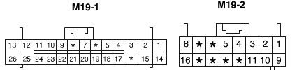
The new MI19-2 plug does have the larger pins as well (1,10,11,12,21 & 22).
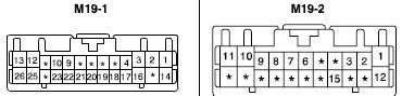
Please note that all plugs are displayed here looking at the front-side. You'll be mostly looking at the back of these plugs so numbering then starts at the top left.
All of the wires of the old MI19-1 and MI19-2 plugs need to be transferred to different locations on the new plugs. Some of them can be transplanted just like that, others need to have another pin (larger or smaller) attached. If that's the case you'll need to cut the wire and solder another pin back on. I recommend starting with the pins that can be relocated as-is before doing the cutting and soldering.
Here's the instructions for the rewiring. The numbers in bold require soldering different pins on. You'll see some wires go from plug MI19-1 to MI19-2 and vice versa, they are indicated as 1.4 for pin 4 on plug 1 or 2.11 for pin 11 on plug 2. I hope this makes sense and these instructions are understandable this way.
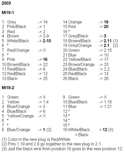
You'll notice there are a few wires that are no longer needed for the F/L2 climate control. Appearantly the new one doesn't use the humidity sensor anymore.
Also look at the layout for the new situation:
There are two signals that the new climate control uses and the old one doesn't. I didn't connect the Water Temperature Sensor wire. It doesn't seem to affect the HVAC operation. If some serious problem arises because of the lack of this signal I'll have to look into retrieving the information from the coolant temperature sensor. I did however connect the Vehicle Speed Sensor wire. This can easily be retrieved from the multi gauge unit.
Multi Gauge Unit plug. Again this is the frontside.

The brown wire (pin 4) is the one you need for the Vehicle Speed Sensor. Use a piece of (preferably brown) wire to attach to this one and solder a small pin at the other end. This goes into pin 8 of the MI19-2 plug. However, the clock & switch module for some reason uses the speed sensor as well so when you do this you should also connect a wire to the clock & switch module plug, which I will now describe in more detail.
The old center facia has all the buttons and clock as separate items sticking in it. The new one has just one clock and switch module which contains the foglight switch, hazard switch, clock and outside temperature display. There is also just one 16-pin plug for it.
Clock & Switch Module plug (frontside)

I was unable to release the small pins in this plug. All I had was a plug with pieces of wires sticking out of it so I just went ahead and soldered all of those wires. You will need the wires from these existing plugs:
Clock plug.
Front Foglight switch plug.
Hazard switch plug.
Here's how to wire them:
M22
1 Pink/Black <- Illumination <- Foglight pin 2
2 Grey <- Illumination <- Foglight pin 1
3 Black <- Ground <- Foglight pin 3
4 Black <- Foglight switch <- Foglight pin 6
5 Brown <- Vehicle Speed Sensor <- Multigauge pin 4
6 *
7 Black <- Ambient Temperature Sensor <- See below !
8 Blue/Orange <- Ambient Temperature Sensor <- See below !
9 *
10 *
11 White <- Hazard switch <- Hazard pin 6
12 Yellow <- Hot In On <- Clock pin 4
13 Red <- Hot At All Times <- Clock pin 2
14 Yellow <- Hot In Acc Or On <- Clock pin 4
15 Orange <- Foglight Indicator <- Foglight pin 4
16 White/Orange <- Foglight switch <- Foglight pin 5
Since the Clock & Switch module displays the ambient temperature it needs this input. Simply take the signal from the climate control. Attach some wire (preferably one black and one blue) to those at the MI19-2 plug pins 3 (blue) and 12 (black). Pin 3 contains the actual signal and 12 is ground to all sensors. Connect the blue wire to the Clock & Switch plug pin 8 and the black wire to pin 7.

That's it! Now just plug everything in again and reinstall the center facia. Don't forget to reconnect the battery
Hopefully this DIY contains enough detail for anyone to work with. If you have questions for me I'd be more than happy to answer to the best of my ability.
One more picture of the final result: